A low-cost precision voltmeter using Arduino
Digital Multimeters (DMM) are an indispensable part of the workbench of an electrical engineer. There is a plethora of multimeters available in the market, with prices ranging from a few hundred BDT to more than a few lacs. However, measuring the voltage using a low-cost DMM accurately is tricky and often unreliable. Most of them allow millivolt measurements in the range of 2000 mv. This tutorial will show how to build a low-cost precision (DC) voltmeter using things probably kicking around your workbench. I have kept things simple with a trade-off that you might notice reading fluctuations after some decimal points, which you can ignore for general purposes. However, you can stabilize readings by employing filtering techniques, which is a topic of our future tutorial.
Required Components
I had almost everything in stock at our CredoSense lab, but here is a list of components needed to build the voltmeter (Table 1). The links provided are for reference only; you can easily source these parts from local vendors.
Table 1: List of required components
| Name | Quantity | Link | Price (US$) |
| Arduino UNO | 1 | https://tinyurl.com/yxzgnmmv | 7.95 |
| ADS1220 ADC IC | 1 | https://tinyurl.com/yxvdlje2 | 8.28 |
| OLED display | 1 | https://tinyurl.com/y53h995k | 6.99 |
| M-M jumper wires | 10 | – | – |
| Breadboard | 1 | – | – |
Level of Difficulty: Beginner
How It Works:
This project’s primary component is the ADS1220 external 24-bit Delta-Sigma Analog to Digital Converter (ADC) IC. The ADS1220 IC is manufactured by Texas Instruments and available from multiple online sources (contact us if you want to buy from us) (datasheet: https://www.ti.com/lit/gpn/ads1220). It has four input channels, each able to perform differential pair reading and single-ended reading. The Arduino communicates ADS1220 via SPI and outputs the converted data in millivolt or microvolt units via the OLED Display attached to it. Since the IC is a 16 pin TSSOP package, it cannot be interfaced directly on breadboards; it needs to be on a PCB. Thankfully, Protocentral has done design works in Autodesk Eagle and made them available on their GitHub repository (https://github.com/Protocentral). Arduino library for ADS1220 is also available on the Protocentral GitHub repository.
The Making:
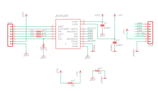
Step-1: Schematic
The schematic for the ADS1220 breakout board (Figure 1) is quite simple and easy to understand and design. Some parts, such as R1, R2, R3, R4, and R6, can be skipped from the design. However, R5 should not be skipped as it is a good practice to connect analog/digital grounds this way.
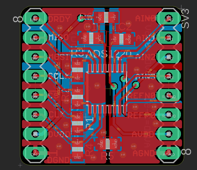
Step-2: PCB
The PCB design files (Figure 2) for the breakout are also available from Protocentral’s GitHub repository. If you want to have fun, go ahead with your favorite PCB designing software, and design your custom breakout board for ADADS1220. Here at CredoSense, we mainly use Eagle. The breakout PCB can be fabricated from any fab house. You can use PCBShopper (https://pcbshopper.com/) to compare printing costs from a variety of manufacturers. Once you’ve selected a manufacturer, you just have to upload Gerber files to their website and place the order!
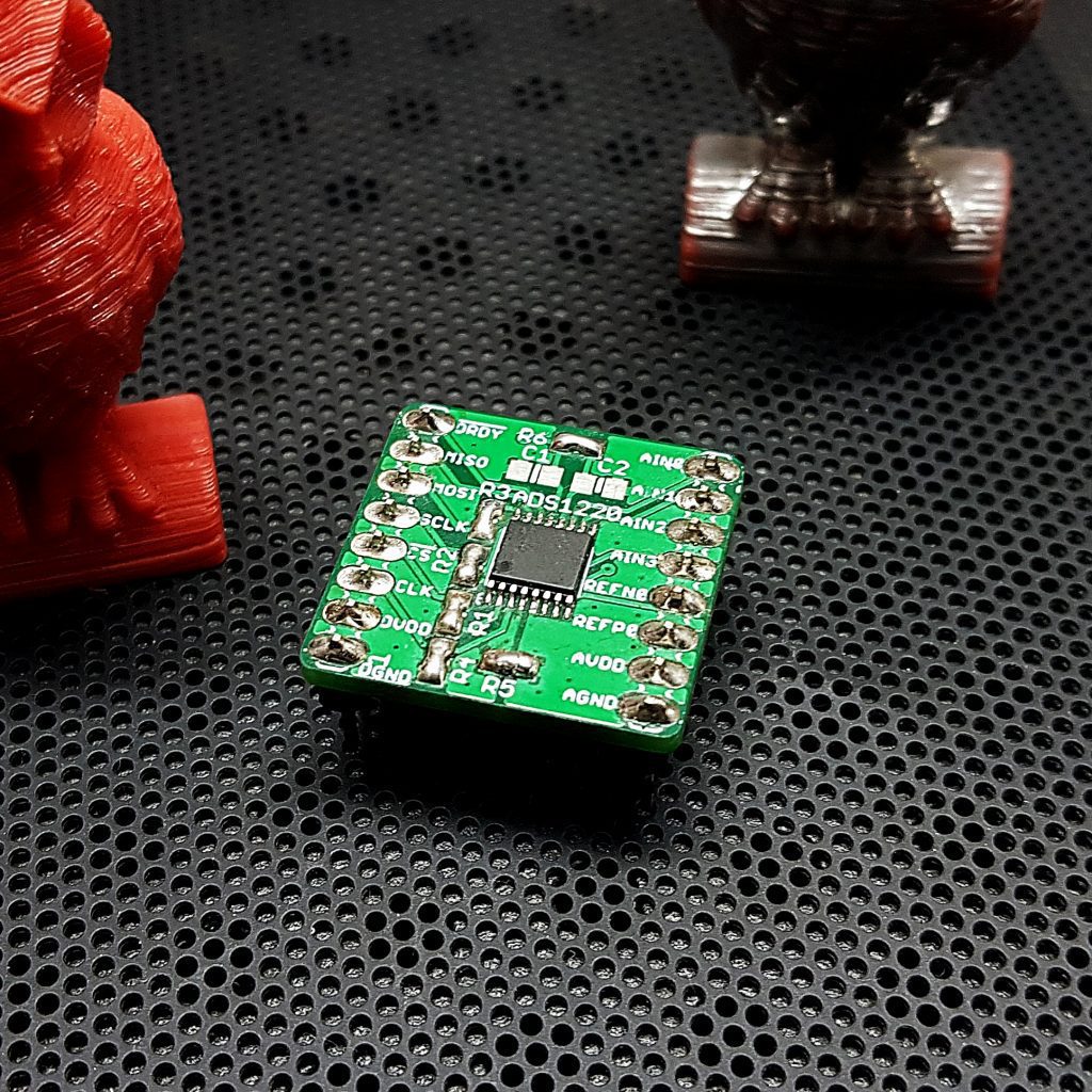
Step-3: Assembly
I have assembled components once I have received the PCB (Figure 3). You do not have to worry about complicated SMT soldering as it is relatively easy to assemble the IC on the PCB. Next, I soldered some jumpers so I could place the PCB on a breadboard. They were 2.54 mm pitched male type straight pin headers.
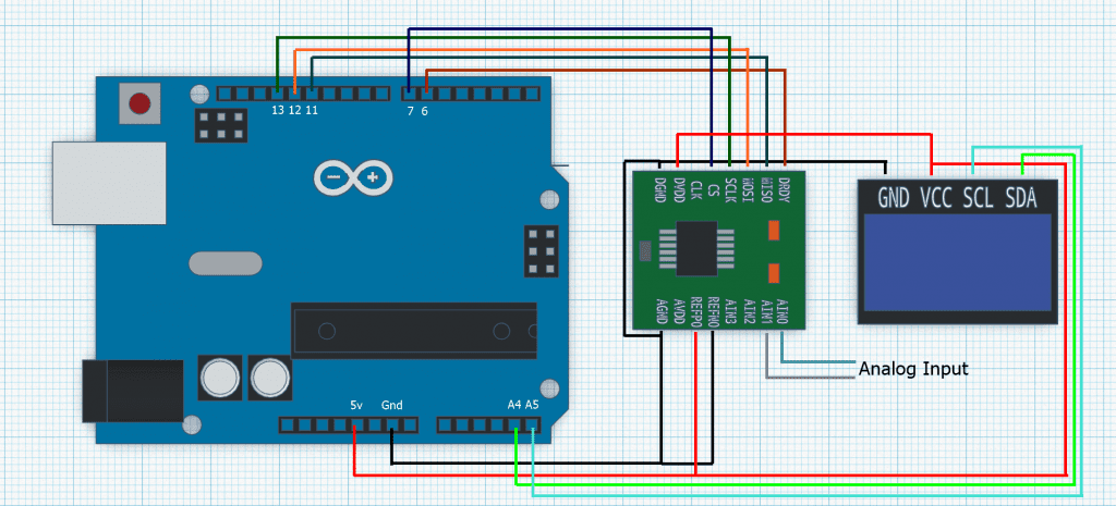
Step-4: Connection
Now it’s time to hook things up! I connected everything according the following diagram (Figure 4):
Step-5: Coding
I have used Arduino IDE to program it. I will provide the links of it and the needed libraries at the end. You can easily find everything you need to build the meter.
#include <Wire.h>
#include <Adafruit_SSD1306.h>
#include <Adafruit_GFX.h>
#define OLED_WIDTH 128
#define OLED_HEIGHT 64
#define OLED_ADDR 0x3C
Adafruit_SSD1306 display(OLED_WIDTH, OLED_HEIGHT);
#include "MegunoLink.h"
#include "Filter.h"
#include "Protocentral_ADS1220.h"
#include <SPI.h>
#define PGA 1 // Programmable Gain = 1
#define VREF 5.06 // External reference input
#define VFSR VREF/PGA
#define FULL_SCALE (((long int)1<<23)-1)
#define ADS1220_CS_PIN 10
#define ADS1220_DRDY_PIN 9
Protocentral_ADS1220 pc_ads1220;
int32_t adc_data;
ExponentialFilter<float> FilteredV(20, 0);
void setup()
{
Serial.begin(115200);
display.begin(SSD1306_SWITCHCAPVCC, OLED_ADDR);
display.clearDisplay();
pc_ads1220.begin(ADS1220_CS_PIN,ADS1220_DRDY_PIN);
pc_ads1220.writeRegister(CONFIG_REG2_ADDRESS, 0x40);
pc_ads1220.set_data_rate(DR_20SPS);
pc_ads1220.set_pga_gain(PGA_GAIN_1);
pc_ads1220.PGA_OFF();
pc_ads1220.set_conv_mode_single_shot(); //Set Single shot mode
display.display();
}
void loop()
{//loop start
float sumMv = 0;
adc_data=pc_ads1220.Read_SingleShot_SingleEnded_WaitForData(MUX_AIN0_AIN1);
float mv = convertToVolt(adc_data);
FilteredV.Filter(mv);
float SmoothV = FilteredV.Current();
Serial.print("\n\nCh1 (mV): ");
Serial.print(SmoothV);
delay(5);
display.clearDisplay();
display.setTextSize(3);
display.setTextColor(WHITE);
display.setCursor(0, 20);
display.println(SmoothV/10000, 5);
display.setTextSize(1);
display.setTextColor(WHITE);
display.setCursor(0, 0);
display.println("Output Voltage (mV):");
display.display();
}//loop end
float convertToVolt(int32_t i32data)
{
return (float)((i32data*VFSR*10000)/FULL_SCALE);
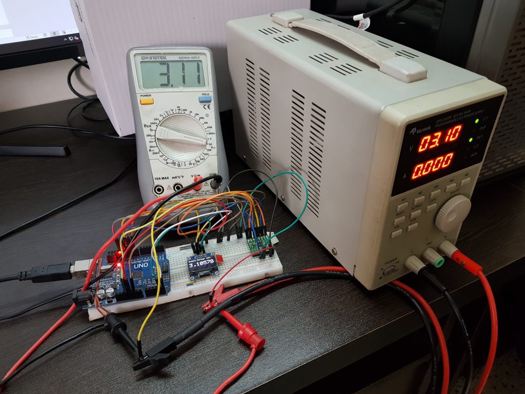
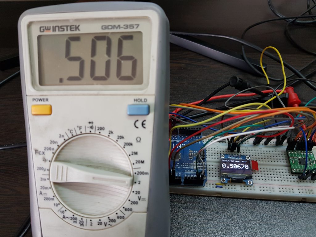
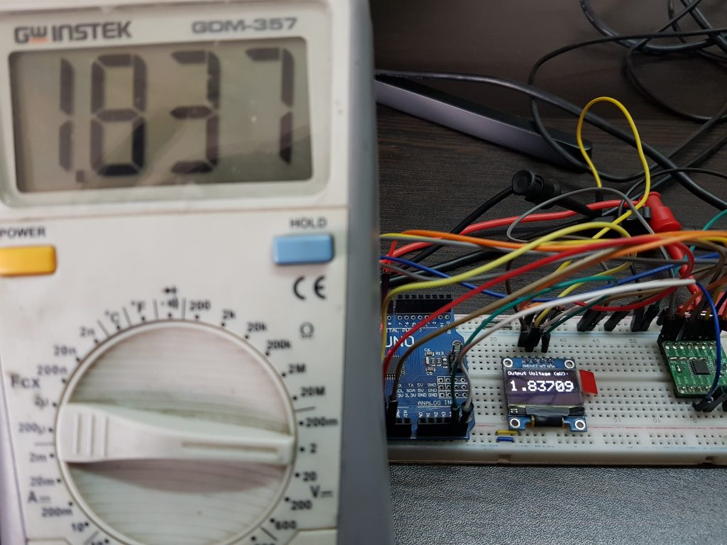
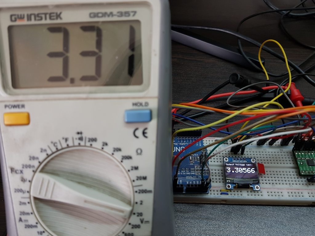
} Now you have a functional low-cost precision voltmeter! Congrats! Ready to measure some DC voltages? Wait! Before you jump in to measure voltages, please read the rest of this paragraph. The IC has an internal reference of 2.048 V as default, which means we can only measure voltage up to that range. Fortunately, it supports an external voltage reference, where a maximum of 7.3 volts can be fed (AVDD has to be 7 V, Figure 1). I only needed up to 5 V, so I supplied 5 volts from the Arduino to the reference input of ADS1220. I suggest using an external voltage reference IC (REF5050) for stable and precise voltage measurements. Arduino’s power rails are not a clean power source and will cause noisy voltage measurements. Additionally, I used channel-1 of ADS1220, where I grounded the AIN0 pin and connected the AIN1 pin to a variable PSU, which was also attached to a GWInstek GDM-357 DMM to crosscheck the voltage measured by our voltmeter (Figure 5). Next, I checked if the measured voltage in our meter and the result in the crosschecking meter are same or not. If there is significant deviation between your meter and the reference meter, then you can calibrate them by slightly changing the VREF value in the code and comparing their results again. This can happen due to bad reference source, breadboard jumpers, unwanted resistances etc. Now you’re ready to measure voltage using the voltmeter you just built!
Result:
Our precision voltmeter has five digits after decimal point to show you the very exact voltage you are measuring. Remember one thing, to measure the voltage correctly you must assign the correct external reference voltage to the VREF variable in code and crosscheck the result with a good quality multimeter if possible. You may calibrate your meter as the mentioned way above if required. If everything is done properly and with some love, I believe you will have your precision voltmeter made at home! Now I will be showing you some measured voltage in our meter built at CredoSense Lab along with a reference meter in parallel to present you how accurate we can go. Let’s see:
For interesting tutorials like this, check back our website or keep an eye on our Facebook and Tweeter pages.
Links:
Libraries:
Arduino IDE: https://www.arduino.cc/en/software/
Adafruit SSD1306: https://github.com/adafruit/Adafruit_SSD1306
Adafruit GFX: https://github.com/adafruit/Adafruit-GFX-Library
Filter Library: https://github.com/Megunolink/MLP
(You may also search these libraries from the Arduino library manager and install directly.)
ADS1220 ADC: https://github.com/Protocentral/Protocentral_ADS1220
Place the library folders from zip files into Documents > Arduino > Libraries.
PCB Files:
Datasheets:
Issues:
- The last two digits seem to be unstable. Might be improved by using dedicated reference source or IC and solid connection by complete PCB.
- Filtering has slightly decreased the data update rate of the meter. You will need to wait few seconds before reading the voltage.
Written by:
Tasnimul Hasan Chowdhury (@Tasn287)
Edited by:
Md Abdul Halim (@BiometHalim) (www.mdhalim.com)
Md Waliur Rahman Prottoy (@Protttoy) (https://sites.google.com/view/waliur-rahman-prottoy/)